

| | detail | |
| |
|
|
|||
|
|||||
| Product
(EPROM Programmer)
|
(Adapter) |
(TSOP48 Socket) | (ZIF-Socket&
Chips) | (PLCC
Extractor) |
PICPRO & MPLAB | |
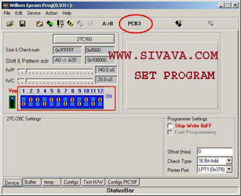
How to use the
EPROM Programmer. |
Set the jumpers to A18 and normal for standard use. Close the 27SF erase jumper only to erase SST27SFXXX devices. The two DIP switch should be both ON,you can select Vpp 21 volt if
the 8.2 Zener diode is mounted: OFF ON. Supply voltage must be 24 Volt
min. for 21 Volt operation. Connect to the printer port with a 25 SubD cable,the cable should not
be longer |
|
* first, delete an entry in the device manager as follows: 1. On the Start Menu, click Start --> Settings --> Control Panel. 2. In the Control Panel, double click the System icon. 3. In the System Properties window, click the Hardware tab. 4. On the Hardware tab, click the Device Manager button. 5. In the Device Manager menu, click View --> Show Hidden Devices. 6. In the device list find the Non-Plug and Play Drivers entry. Click the 'plus' sign on the left of the entry to expand the list. 7. Find the dlportio entry and right-click it. Click on Uninstall in the context menu that appears. If it is not there already, then no problem carry on. * in the registry, I deleted entries that had to do with dlportio. search for dlportio and delete any folder that refers to it. I think this just removes any OS reference to dlportio, so like you are starting fresh. * download TLDPortIO from the web * install the drivers
using the utility--play around with it a bit--the point is to get the
DLL and SYS file installed in the system and start a service. Test the connection with TestHardware In the program set to 'PCB' (only
needed with first use) Warning: never insert an eprom
when you haven't started the program yet and the Vpp and Vcc leds are
still burning. Programming can fail in different ways: Normally you should not change tWP and tWC unless you know what you
are doing. The configs section give an overview of all settings and parameters. If you need PIC in circuit programming, you can use a DIP connector
for the 18 pin PIC 16F84 socket(5 gnd.,12 clock,13 data i/o,14 Vcc). |
Email
: webmaster@sivava.com
Copyright © 2002-2004 sivava.com All rights reserved. Last Update: February 27 th 2004 |