 I
have build my own programmer. This device can program the AT89C51 and
works with it. So it can be easily adapted to programming other devices by
itself.
I
have build my own programmer. This device can program the AT89C51 and
works with it. So it can be easily adapted to programming other devices by
itself.
I
have build my own programmer. This device can program the AT89C51 and
works with it. So it can be easily adapted to programming other devices by
itself.
The Atmel Flash devices are ideal for developing, since they can be reprogrammed easy, often and fast. You need only 1 or 2 devices in low cost plastic case for developing. In contrast you need 10 or more high cost windowed devices if you must develop with EPROM devices (e.g. Phillips 87C751).
The AT89C2051 is the smallest 8051 member with full resources (128 Byte RAM,
2 Timer, UART). Only the Flash size and pin count is reduced (2kByte, 20
pin case: 15 IO pins available).
Now I have build a programmer for these 20 pin devices working
with the AT89C2051: The AT89C2051
Programmer
The programmer and the PC are connected via a serial port (COM1...4). No
Interrupt is used since every data byte from the programmer must be receipt
by the PC. So this program can also run under WINDOWS without data loss.
Today following devices can be programmed:
The using is quite simple. The example file "proflash.bat" can be used for
calling automatically after generating hex file to program in batch mode.
In this case the target must be placed in the programmer before compiling
started. Or you place "uniprog.ini" in the same directory with the "uniprog.exe"
file and make all programming steps manually.
On AVR devices the FLASH and EEPROM are programmed together. If only one
name is given, the second name for the EEPROM hex file is build by exchanging
the extension with ".eep". You can also give 2 different names for both.
On using a comma to separate you can define one or both names empty.
To select the device you can use the autoselect feature. You can also select
it by using the up -or 'u'-key or down- or 'd'-key (using characters 'd'
or 'u' in batch mode recommend).
The programmer is tested under DOS or WINDOWS (3.xx or 95). A 386SX or higher
CPU is needed.
These are free for non commercial using only !
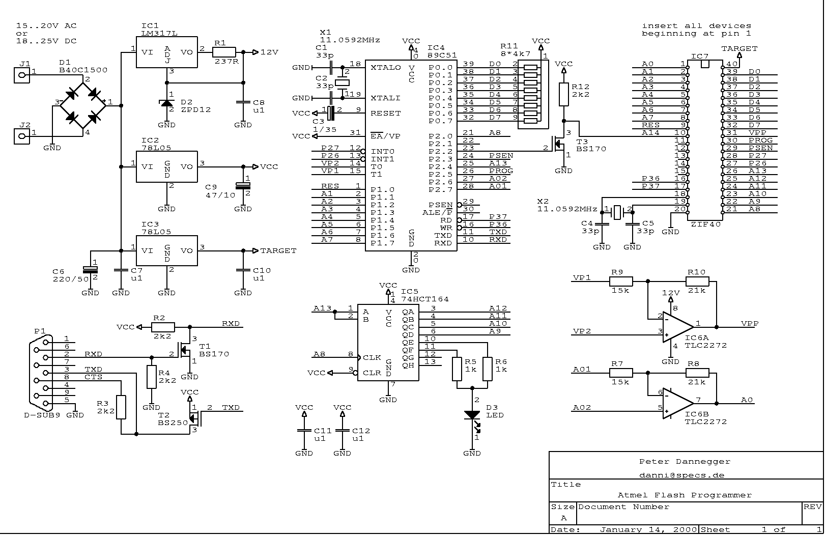
There is no pcb available. Since most connections are from the programmer
(AT89C51) to the same pin of the target (ziff-socket), it can be easily build
with an universal pcb. Only few other devices are needed.
To prevent malfunction on using different versions of the programmer, load
all needed documents together.
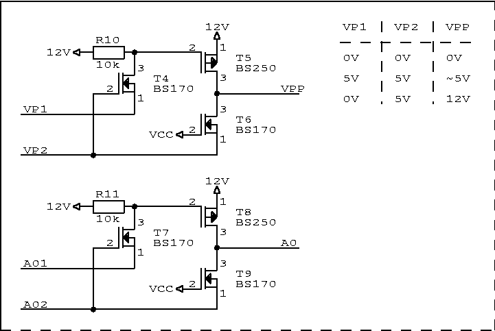
Important: The Opamp
(TLC2272)
must meet following parameters:
- Rail to rail output,
- Input range include negative rail,
- Slew rate 3.6V/µs or higher.
If you have problems getting the TLC2272 you can try the following replacement:
Data Sheets:
If you have problems to get data from any device look at the manufacturer
or distributor e.g. Farnell
E.g. data sheets of:
BS170,
BS250
| 2 | --------- | 3 |
| 3 | --------- | 2 |
| 4 | --------- | 6 |
| 5 | --------- | 5 |
| 6 | --------- | 4 |
| 7 | --------- | 8 |
| 8 | --------- | 7 |
There are 3 ways to get the preprogrammed AT89C51 inside the programmer:
1. Ask a friend in a school or company which have access to a programmer.
2. Most salesman offers also a programming service for a little more money.
You must only put the hex file (proflash.hex) to a disk and send it him.
3. Use a AT89S8252 at first and program it over the parallel port.
Look at
http://www.fmi.cz/jak/prog.html
for more informations.
Please understand that I can't sell it.
No errors known.
I have received over 100 positive feedbacks. So it seems working stable.
some points to check:
- after power on the LED must flashing short exact every second. Otherwiese
the crystal is wrong
- during programming the LED light permanently
- the hex-file was correct burned in the programmer (IC4)
- the crystal was correct (11.0592MHZ) for right baud rate and oscillating
(check with oscilloscope)
- EA was connect to VCC (internal program execution)
- VCC was applied, reset was done (by C3)
- RS232 level shifter works
The PC software try permanetly send to the programmer until it answered right.
This can easy be checked with an oscilloscope:
Check signals on P1/pin2, IC4/pin 10, IC4 /pin11, P1/pin3. P1/pin8 must give
about -12V.
Author: Peter Dannegger
E-mail: danni@specs.de Text only (not HTML) required !
![]()