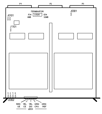
Sun-4/260/280
| 501-1102 |
501-1254 |
501-1451 |
501-1576 |
| 8MB ECC |
32MB ECC |
32MB ECC |
16MB ECC |

Power
| 8MB |
12.3 Amps @ +5Vdc
61.5 Watts |
| 32MB |
14.0 Amps @ +5Vdc
70.0 Watts |
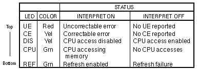
Memory Board LEDs

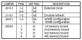
Jumper Settings

Notes
- The Sun 4200 CPU requires EPROM 3.0 or greater when more than two 16MB ECC
memory boards are installed.
- 501-1092 or 501-1117 BackpIanes: Install a single memory board in
Slot 6 with a 220/270 Terminator, 120-1613-01, installed at location U1203.
Remove the terminator when expansion memory boards are installed in Slots 2,
3, 4, and 5.
- 501-1439 or 501-1498 Backplanes: Install a 220/270 Terminator 120-1613-01,
at location U1203 on the memory board in Slot 1. If placement results in
memory boards on both sides of the CPU, remove the terminator at location U1411
on the Sun 3400 CPU, and install terminators on the memory boards in Slots 1
and 7.
- The 8MB memory board must be >=501-1102-11 to use with the Sun 3400CPU,
the FPA, and the FPA+.
- The 501-1451 32MB board >=501-1451-03 to use with the 501-1576 6MB
memory board.
- Remove jumpers P10, P11, P12, and P13 from the 501-1598 and 501-1832
backplanes when the Sun 3400 board set is installed.
References
- Sun 501-1102 Memory Board Configuration Procedures, 813-2018.
- Installation Notes for the 32MB Memory Board, 800-2123.
- 16 MB ECC Memory Board Installation and Configuration Manual,
813-1066.
Last updated: December 2, 1996
|


