| Sun System Handbook | Home | Systems | Components | General Info | Search | Feedback | |
|
|
||
|
| ||
|
|
|
|||||||||||||
|
|
||||||||||||
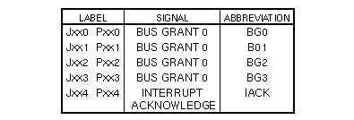
Volume I: BackplaneBackplane InformationThis section contains bus signal charts and backplane layout illustrations. VMEbus BackplaneCardcage slot numbers are stamped, printed, or labeled on the sheet metal near the card ejectors. VMEbus backplane jumpers are silk-screened on the cardcage as Px00, Px01, Px02, Px03, and Px04 or Jx00, Jx01, Jx02, Jx03, and Jx04; where x represents the card slot number. These jumpers control VMEbus signals BUS GRANT 0-3 IN (BG0-3IN) to BUS GRANT 0-3 OUT (BG0-3 OUT), and INTERRUPT ACKNOWLEDGE IN (IACKIN) to INTERRUPT ACKNOWLEDGE OUT (IACKOUT). The VMEbus signals are referred to as BG0, BG1, BG2, BG3, and IACK in this section.
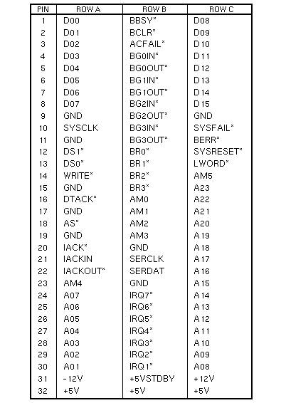
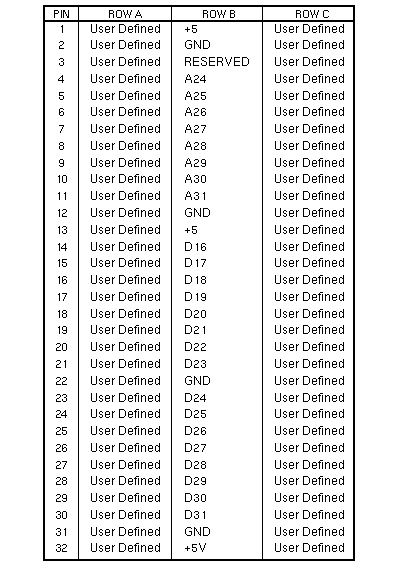
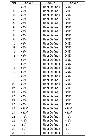
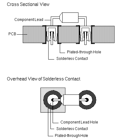
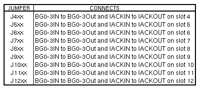
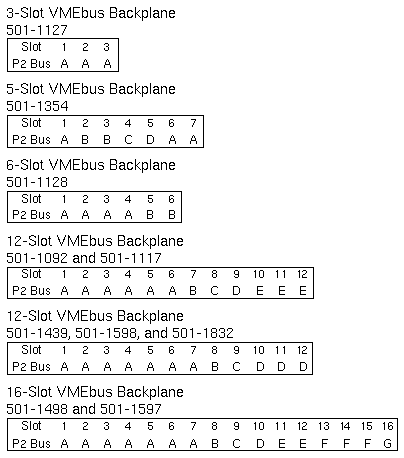
VMEbus SignalsThe VMEbus consists of signals on J1/P1 Row A, J1/P1 Row B, J1/P1 Row C, and J2/P2 Row B. P2 Bus SignalsThe Sun P2 Bus consists of signals on J2/P2 Row A, J2/P2 Row C, and J3/P3 Row B. VMEbus J1/P1 Pinouts VMEbus J2/P2 Pinouts VMEbus J3/P3 Pinouts Pressfit BackplanesPressfit Backplane production began in June 1987. Solderless contacts are machine pressed into plated-through holes on printed circuit boards. Component leads installed into the solderless contacts are held in place by a tapered entry, multi-finger contact design. 501-1439, 501-1598, and 501-1832 12-Slot BackplanesThe Sun P2 bus connects cardcage Slots 1 through 7 to each other, and cardcage Slots 10, 11, and 12 to each other. In addition to the Sun P2 bus and the VMEbus, the 12-slot backplane has a private Internal bus that connects Slots 1, 2, and 3 as shown below. J1/P1, Rows A, B, and C, on Slots 1, 2, and 3 are not connected to the VMEbus. Boards that use the VMEbus cannot be used in Slots 1, 2, or 3. J2/P2, Row B, is connected between Slots 1 through 7. The 501-1439 Backplane terminates J2/P2, Row C, Pins 75 and 96 with a 40.2W resistor and a 47pf capacitor. The 501-1598 and 501-1832 Backplanes terminate J2/P2, Row C, Pins 75 and 96 with a 200W resistor. Termination is jumper selectable. The Sun 4400 CPU is not supported in the 501-1439 Backplane. The function of the backplane jumpers is shown below. Backplane Sun P2 or Private Bus ConnectionBackplane slots that share an adjacent P2 bus are marked with the same letter in the charts below. | ||||||||||||
|
||||||||||||