Ultra 30 / Netra t 1100
A16

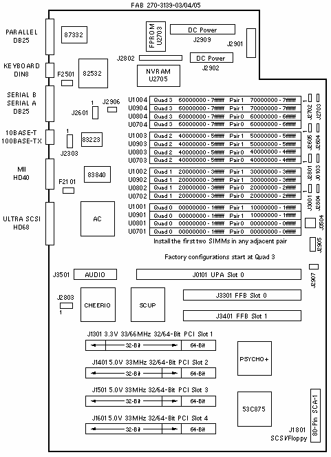
FAB 270-3139-03/04/05 Jumper Settings
| JUMPER |
PINS |
SETTING |
DESCRIPTION |
| J0103 |
1-2
2-3 |
In
In |
Bypass CPU in scan chain
Include CPU in scan chain (default) |
| J2604 |
1-2
2-3 |
In
In |
RS-232
RS-423 (default) |
| J2605 |
1-2
2-3 |
In
In |
RS-232
RS-423 (default) |
| J2702 |
1-2
2-3 |
In
In |
Select FPROM (default)
Select ROMBO |
| J2703 |
1-2
2-3 |
In
In |
FPROM write protect (default)
FPROM write enable |
| J2804 |
1-2
2-3 |
In
In |
FPROM high half booting
FPROM low half booting (default) |
| J3001 |
1-2
2-3 |
In
In |
÷3 mode (250MHZ/300MHz)
÷2 mode (167MHz/200MHz) |
Miscellaneous Connectors
| CONNECTOR |
PINS |
DESCRIPTION |
| J1801 |
1-80 |
SCSI and Floppy Bus |
| J2303 |
1-8 |
Ethernet test (factory use) |
| J2602 |
1-8 |
Serial test (factory use) |
| J2801 |
1-3 |
Button XIR/POR (factory use) |
| J2802 |
1-32 |
ROMBO (factory use) |
| J2803 |
1-8 |
JSCC (factory use) |
J2901
J2901 |
1-20
1-16 |
Sense from Power Supply (FAB 03)
Sense from Power Supply (FAB 04/05) |
| J2902 |
1-8 |
DC Power from Power Supply |
| J2906 |
1-4 |
Rear Fan power |
| J2907 |
1-2 |
Front Fan power |
| J2909 |
1-12 |
DC Power from Power Supply |
| J3504 |
1-4 |
On/Off Switch |

Configured System Boards
PART
NUMBER |
MEMORY
SIZE |
SIMM
SIZE |
NUMBER
SIMMs |
SPARC
MODULE |
MODULE
CACHE |
| 501-4101 |
128MB |
32MB |
4 |
250MHz |
1MB |
| 501-4340 |
128MB |
32MB |
4 |
300MHz |
2MB |
| 501-4341 |
512MB |
128MB |
4 |
300MHz |
2MB |
System Codenames
| System |
Codename |
| Ultra 30 |
Quark |
| Netra t 1100 |
Lightweight |
Notes
- The minimum operating system is Solaris 2.5.1 Hardware: 4/97.
- The flash PROM is soldered to the system board.
- Use the Flash PROM Programming Utility to update the flash PROM.
Graphics Notes
- FFB2+ is not compatible with 300MHz Module 501-4196.
- FFB2+ is not compatible with 300MHz Module <=501-4849-02.
- Elite3D is not compatible with 300MHz Module 501-4196.
- Elite3D is not compatible with 300MHz Module <=501-4849-02.
Memory Notes
- Two DIMMs form a pair. Two pairs of DIMMs form a quad.
- The minimum memory requirement is two DIMMs in any adjacent pair.
- DIMMs can be installed in any order of pairs.
- Interleaving requires a fully populated quad.
- Each quad addresses 512MB of memory.
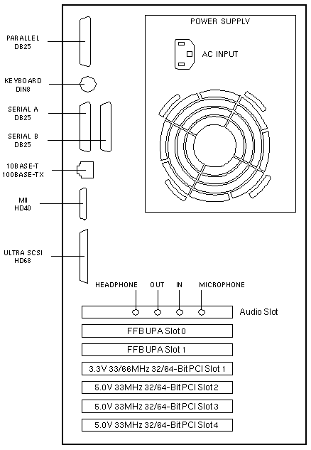
PCI Slot Numbering
| SLOT |
BUS |
DEVICE TREE |
| 1 |
A |
pci@1f,2000/*@1,* |
| 2 |
B |
pci@1f,4000/*@2,* |
| 3 |
B |
pci@1f,4000/*@4,* |
| 4 |
B |
pci@1f,4000/*@5,* |
PCI Bus B shares the address/data bus with onboard Audio, Ethernet, Flash,
Floppy, Keyboard, Mouse, NVRAM, Parallel, SCSI, and Serial devices.
References
 Ultra 30 Service Manual, 802-7719.
- Ultra 30 ShowMe How CD-ROM, 704-5681.
 Flash PROM Programming Guide, 802-3233.
|

