Using USB Devices (Overview/Tasks)
This chapter provides an overview of Universal Serial Bus (USB) devices and step-by-step instructions for using USB devices in the Solaris environment.
For information on the procedures associated with using USB devices, see the following:
This is a list of the overview information in this chapter.
For general information about dynamic reconfiguration and hot-plugging, see Chapter 27, Dynamically Configuring Devices (Tasks).
For information on configuring USB printers, see "What's New in Printing?" in System Administration Guide: Advanced Administration.
Overview of USB Devices
Universal Serial Bus (USB) was developed by the PC industry to provide a low-cost solution for attaching peripheral devices, such as keyboards, mouse devices, and printers, to a system.
USB connectors are designed to fit only one type of cable, one way. Devices can connect to hub devices, which connect several devices, including other hub devices. The primary design motivation for USB was to alleviate the need for multiple connector types for different devices, thereby reducing the clutter on the back panel of a system. Additional advantages of using USB devices are as follows:
USB devices are hot-pluggable. For more information, see "Hot-Plugging USB Devices".
Supports a maximum of 126 devices per host controller in the Solaris environment.
Supports a maximum of 12 Mbit/sec data transfer.
Supports low speed (1.5 Mbit/sec) and full speed (12 Mbit/sec) devices.
Supports Solaris Ready USB PCI controllers. For more information, see http://www.sun.com/io.
The bus can be easily extended by adding low-cost external hubs. Hubs can be connected to hubs to form a tree topology.
Sun Microsystems support for USB devices includes the following:
USB 1.1 devices are supported in the Solaris 9 environment.
Sun Blade™ 100 and Sun Blade 1000 systems that run the Solaris 8 10/00, 1/01, 4/01, 7/01, 10/01, 2/02 and Solaris 9 releases provide USB device support.
Netra™ X1/T1 and Sunfire 280R systems that run the Solaris 9 release.
IA based systems that run the Solaris 8 and Solaris 9 Intel Platform Editions provide USB support also. For more information, see scsa2usb(7D).
This table lists specific USB devices that are supported in the Solaris environment.
USB Devices | Systems Supported |
|---|---|
HID control on audio devices | SPARC based and IA based systems. |
Hubs | SPARC based and IA based systems. |
Keyboards and mouse devices | SPARC based systems with Sun USB support based on the ohci controller. IA based systems with a USB bus based on the uhci controller. Only on-board USB controllers are supported. |
Mass storage devices | SPARC based and IA based systems. |
Printers | SPARC based and IA based systems. |
Speakers and microphones | SPARC based and IA based systems. |
Commonly Used USB Acronyms
The following table describes the USB acronyms that are used in the Solaris environment. For a complete description of USB components and acronyms, go to http://www.usb.org.
Acronym | Definition |
|---|---|
USB | Universal Serial Bus |
USBA | Universal Serial Bus Architecture (Solaris) |
USBAI | USBA Client Driver Interface (Solaris) |
HCD | USB host controller driver |
USB Bus Description
The USB specification is openly available and free of royalties. The specification defines the electrical and mechanical interfaces of the bus and the connectors.
USB employs a topology in which hubs provide attachment points for USB devices. The host controller contains the root hub, which is the origin of all USB ports in the system. For more information about hubs, see "USB Host Controller and Root Hub".
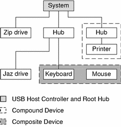
Figure 28-1 USB Physical Device Hierarchy

Figure 28-1 shows a system with three active USB ports. The first USB port has a Zip drive that does not have an embedded hub, so you cannot attach additional devices. The second USB port has a hub with a Jaz drive and a composite keyboard/mouse device connected. One port from the secondary hub has a keyboard with an embedded hub where the mouse is attached.
Figure 28-1 also shows an example of a hub and printer as a compound device. Both the hub and the printer are enclosed in the same plastic case, but the hub and the printer have separate USB bus addresses. The same diagram shows an example of a composite device. The composite keyboard and mouse are also enclosed in the same plastic case, but they have the same USB bus address. A cable connects the USB mouse to the composite keyboard/controller in this figure.
The device tree path name for some of the devices that are displayed in Figure 28-1 are listed in this table.
Zip drive | /pci@1f,4000/usb@5/storage@1 |
Keyboard | /pci@1f,4000/usb@5/hub@2/device@1/keyboard@0 |
Mouse | /pci@1f,4000/usb@5/hub@2/device@1/mouse@1 |
Jaz drive | /pci@1f,4000/usb@5/hub@2/storage@3 |
Printer | /pci@1f,4000/usb@5/hub@3/printer@1 |


